ANSYS Workbench
Thermal, Fluid, and Structural Load Simulations on ANSYS Fluent and Static Structure
Conjugate Heat Transfer - Electronics Cooling
-
At T_in = 60°C and 0.01 ≤ Vin ≤ 0.08m/s,
Tout ∝ Vin represents the effect of conductive heat transfer between the fluid and the solid -
Difference in T_out is ~ 25°C considering the effect of buoyancy
-
The heat sink accounts for ~33% of the total heat transfer with Boussinesq’s method as compared to ~25% in the case of constant density
-
FC3283 shows better heat dissipation as compared to Mineral-Oil. Due to β_FC>β_MO and Cp_FC<Cp_MO

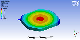
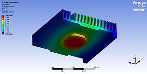
Thermal Analysis of Heat Sink on Intel Atom
-
3D steady-state thermal analysis of heat sink on Intel Atom dual-core chip to demonstrate the cooling effect of the heat sink in electronics
-
Copper heat sink on Aluminum chip, with ambient air at 22°C
-
Power dissipated by the chip is 6.5 W and the operating temperature is -35°C ~ 80°C
-
Maximum temperature without heat sink: 84°C
-
Maximum temperature with heat sink: 24°C


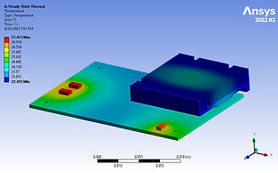
PCB Thermal Analysis
-
3D steady-state thermal analysis of PCB
-
Copper heat sink on Aluminum chip and 3 1W high power components on FR-4 Board with ambient air at 22°C and 55 W/m*K

Three Phase Transient Flow
-
Three phase transient simulation representing water droplet falling into liquid diesel in an air filled domain
-
Total time: 0.7 s | Time step: 0.001 s
-
Volume of Fluid method | Laminar Flow
-
Domain size: 25cm x 25cm
Two Phase Transient Flow 3D
-
Glycerine droplet flowing over a 30 degree inclined plane under influence of gravity
-
Total time: 0.2 s | Time step: 0.0005 s
-
V.O.F. method | Laminar Flow
-
Domain size: 0.18m x 0.08m x 0.04m
-
Droplet radius: 0.02m

Two Phase Transient Flow 2D
-
Methane leakage from a pressurized chamber
-
Total time: 6 s | Time step: 0.01 s
-
V.O.F. method | K-Omega model
-
Domain size: 60m x 35m
-
Boundary conditions: Pressure Inlet = 50 Pa and
surrounding Pressure Outlet = 0 Pa -
Additional case:
Wind Velocity is given by u = 0.6 y – 0.02 y^2
Compressible Transient Flow
-
3D Model of interconnected pressure cylinder
-
Initial Condition: Small cylinder = 10200 Pa
-
Large cylinder = 10000 Pa and Temperature = 300 K
-
Fluid: Air (ideal gas)
-
k-omega turbulence model | density based solver study the density, temperature, and velocity for
t = 0 - 0.05 secs -
CAD Model created using Solidworks.
-
Domain size: 0.7 m x 0.2 m and diameter = 0.2 m
-
Total time: 0.05 s | Time step: 0.0005 s
Thermo-Fluid: Viscous Heating
-
3D thermo-fluid analysis of Engine oil flowing through a coil at 1 m/s, 2 m/s, and 4 m/s
-
Laminar Model | Velocity inlet | Pressure outlet
-
3D CAD Helical pipe model created using Solidworks
-
Helix: X(τ) = R cos(τ) | Y(τ) = R sin(τ) | Z(τ) = C τ
-
Pipe diameter = 0.08 m, Helix radius = 0.3 m
-
Another simulation with Liq. Water and uniform heat flux of 700 W/m^2 on wall was analyzed.
-
This was done to study the effect of flow velocity on fluid temperature with inlet velocities 0.008 m/s, 0.016 m/s, 0.032 m/s, and 0.064 m/s.
-
Observed linear proportionality between flow velocity and temperature due to viscous heating